
Two magnetic pads both rated 25W can feel a world apart. One holds 25W steadily; the other looks fine for ten minutes, then runs hot and throttles. Buyers usually call that false advertising, but most of the gap lives in the circuit. Wireless charging is, at heart, two coils tuned to one resonant frequency and then matched on top of that resonance.
LC resonance puts the coils on the right frequency
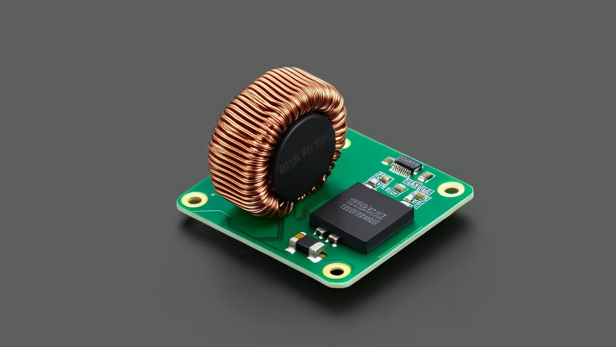
The transmitter coil and the receiver coil are each an inductor, and each pairs with a compensation capacitor to form an LC tank. The resonant frequency is simple arithmetic: f0 is one over two pi times the square root of LC. At that frequency the inductive and capacitive reactances cancel, voltage and current stay in phase, no reactive power sloshes back and forth, and transfer efficiency peaks. Consumer wireless charging usually runs between 100 and 205 kilohertz, while automotive systems follow a separate standard at 85 kilohertz.
Matching the frequency is not enough on its own. Transfer efficiency between coils has a neat expression: k squared times Q1 times Q2, divided by one plus the same product. Here k is the coupling coefficient, meaning how tightly the two coils link magnetically, and Q is the quality factor, equal to angular frequency times inductance divided by coil resistance, which measures how little loss the coil itself has. The formula says one thing: go faster by coupling tighter or losing less in the coil, not by pushing more watts.
Misalign and efficiency drops, so the system has to retune
This is why magnetic alignment matters. Shift the coils sideways and the coupling coefficient falls, taking efficiency with it. Magnets lock k in place, which is what lets 25W survive at a safe temperature. Beyond alignment, two long-term engineering jobs remain.
The first is frequency tracking. The load changes as a phone fills and its charging curve shifts, and the mutual inductance drifts with gap and offset, so the system keeps probing primary voltage and current, checking phase, and nudging the operating frequency to a better point. Some topologies deliberately run slightly above resonance, using that small reactive margin for soft switching, which in testing has added several percentage points of efficiency.
The second is impedance matching. The closer the load impedance sits to the source, the smaller the reflection and the more power actually gets delivered. Mature designs identify the load online and retune the matching network while charging. One side effect is worth knowing: when several receivers couple to one transmitter, very tight coupling splits the resonance curve into two peaks, a phenomenon called bifurcation. Multi-device chargers need dedicated scheduling logic to handle it, or they end up slower the closer a device gets.
One-line advice: buying a 25W magnetic pad is really buying a tuned resonant system plus a thermal design. Sharp alignment, well-made coils and live frequency tracking are what let the rated 25W reach the phone. Without them, the spec sheet is just a number.
© SWPO. All rights reserved.